How the VRD Works
Also see the VRD animations by Quin Smithwick
Using the VRD technology it is possible to build a display with the following characteristics:
In a conventional display a real image is produced. The real image is
either viewed directly or projected through an optical system and the
resulting virtual image is viewed. With the VRD no real image is ever
produced. Instead, an image is formed directly on the retina of the
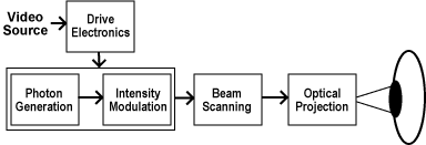
user's eye. A block diagram of the VRD is shown below.
To create an image with the VRD a photon source (or three sources in the
case of a color display) is used to generate a coherent beam of light. The
use of a coherent source (such as a laser diode) allows the system to draw
a diffraction limited spot on the retina. The light beam is intensity
modulated to match the intensity of the image being rendered. The
modulation can be accomplished after the beam is generated or, if the
source has enough modulation bandwidth as is the case with a laser diode,
the source can be modulated directly.
The resulting modulated beam is then scanned to place each image point, or
pixel, at the proper position on the retina. A variety of scan patterns
are possible. The scanner could be used in a calligraphic mode, in which
the lines that form the image are drawn directly, or in a raster mode,
much like standard computer monitors or television. Our development
focuses on the raster method of scanning an image and allows the VRD to be
driven by standard video sources. To draw the raster, a horizontal scanner
moves the beam to draw a row of pixels. The vertical scanner then moves
the beam to the next line where another row of pixels is drawn.
In the original prototype the faster horizontal scanning is
accomplished with an acousto-optical modulator and the vertical scanning
with a galvanometer to produce a 1280 pixel by 1024 line raster that is
updated at 72 Hertz. The use of the acousto-optical modulator does,
however, come with a number of drawbacks. First, it requires optics to
shape the input beam for deflection and then additional optics to reform
the output beam to the desired shape. Second, it requires complex drive
electronics that operate at a very high frequency. Next, it has a very
limited scan angle (4 degrees in our current prototype) such that
additional optics are needed to increase the angle to the desired
field-of-view. Due to the optical invariant, this optical increase in
angle comes with the penalty of decreased beam diameter which leads to a
small exit pupil. The small exit pupil necessitates precise alignment with
the eye for an image to be visible. Finally, the acousto-optical modulator
is expensive and will not, in the foreseeable future, allow us to reach
our cost goals for a complete VRD system.
To overcome the limitations of the acousto-optical modulator HITL
engineers have developed a proprietary mechanical resonant scanner. This
scanner provides both horizontal and vertical scanning, with large scan
angles, in a miniaturized package. The estimated recurring cost of this
scanner will allow the VRD system to be priced competitively with other
displays. A prototype VRD using the new mechanical resonant scanner has
been developed and is currently being refined.
After scanning, the optical beam must be properly projected into the eye.
The goal is for the exit pupil of the VRD to be coplanar with the entrance
pupil of the eye. The lens of the eye will then focus this collimated
light beam on the retina to form a spot. The position on the retina where
the eye focuses a spot is determined by the angle at which light enters
the eye. This angle is determined by the scanners and is constantly
varying in a raster pattern. The intensity of the focused spot is
determined by the intensity modulation of the light beam. The intensity
modulated moving spot focused on the retina forms an image.
The final portion of the system is the drive electronics which must
synchronize the scanners with the intensity modulators to form a stable
image.
For 3-D viewing an image will be projected into both of the user's eyes.
Each image will be created from a slightly different view point to create
a stereo pair. With the VRD, it is also possible to vary the focus of each
pixel in the image such that a true 3-D image is created. Thus, the VRD
has the ability to generate an inclusive, high resolution 3-D visual
environment in a device the size of conventional eyeglasses.
|

