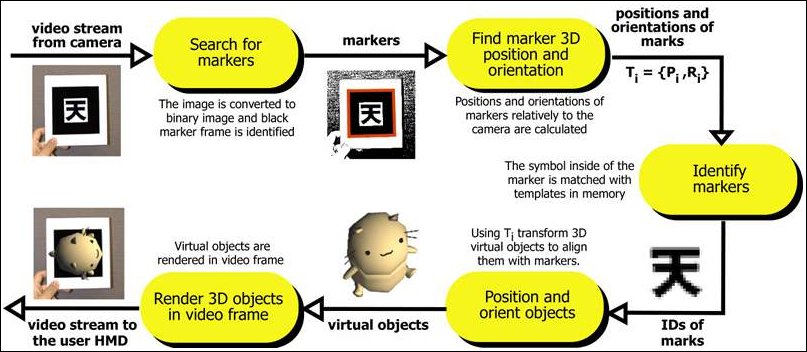
- The camera captures video of the real world and sends it to the computer.
- Software on the computer searches through each video frame for any square shapes.
- If a square is found, the software uses some mathematics to calculate the position of the camera relative to the black square.
- Once the position of the camera is known a computer graphics model is drawn from that same position.
- This model is drawn on top of the video of the real world and so appears stuck on the square marker.
- The final output is shown back in the handheld display, so when the user looks through the display they see graphics overlaid on the real world.
There are also range issues. The larger the physical pattern the further away the pattern can be detected and so the great volume the user can be tracked in. Table 1 shows some typical maximum ranges for square markers of different sizes. These results were gathered by making maker patterns of a range of different sizes (length on a side), placing them perpendicular to the camera and moving the camera back until the virtual objects on the squares disappeared.
| Pattern Size (inches) | Usable Range (inches) |
| 2.75 | 16 |
| 3.50 | 25 |
| 4.25 | 34 |
| 7.37 | 50 |
Table 1: Tracking range for different sized patterns.
Tracking is also affected by the marker orientation relative to the camera. As the markers become more tilted and horizontal, less and less of the center patterns are visible and so the recognition becomes more unreliable.
Finally, the tracking results are also affected by lighting conditions. Overhead lights may create reflections and glare spots on a paper marker and so make it more difficult to find the marker square. To reduce the glare patterns can be made from more non-reflective material. For example, by gluing black velvet fabric to a white base. The 'fuzzy' velvet paper available at craft shops also works very well.
You will find more informations on computer vision principle at this page, or more informations on performance at this page.