This page presents how use utility programs included with ARToolKit to calibrate your video camera. ARToolKit provides two calibration approaches:
- Two Step Calibration Approach
Difficult to use, but results in better accuracy (better for 3D measurement). - One Step Calibration Approach
Easy to use, giving accuracy good enough for image overlay.
 |
 |
The important camera properties that must be measured include the center point of the camera image, the lens distortion and the camera focal length. The program calib_dist is used to measure the image center point and lens distortion, while calib_param produces the other camera properties. Both of these programs can be found in the bin directory and their source is in the utils/calib_dist and utils/calib_cparam directories.
The calib_dist program should be run first and then calib_cparam, since calib_cparam uses the output of calib_dist. In the remainder of this section we explain how to run each of these programs.
Running calib_dist
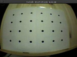
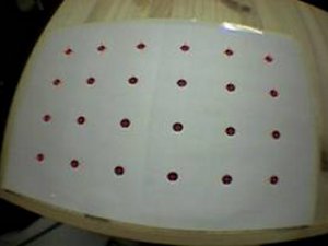
calib_dist uses the calib_dist.pdf image of a pattern of 6 x 4 dots spaced equally apart. When viewed through the camera lens, lens distortion causes a pin cushion effect that produces uneven spacing between the dots in the camera image. The calib_dist program measures the spacing between the dots and uses this information to calculate the lens distortion.
Run the calib_dist program from the command prompt. You will obtain this output in your terminal:
> calib_dist
Image size (x,y) = (720,486)

-----------
Mouse Button
Left : Grab image.
Right : Quit.
-----------
A window will appear showing live video. Point the camera at the calibration pattern so that all the dots are in view and click the left mouse button. This freezes the video image, as shown in Figure 2. Now click and drag on the image with the left mouse button to draw a black rectangle over each dot. Start with the dot closest to the top left hand corner of the image and continue until all the dots are found. The dots must be covered in the following order:
1   2  3  4  5  6
7   8  9 10 11 12
13 14 15 16 17 18
19 20 21 22 23 24
After each rectangle is drawn image processing software will find the dot enclosed by the rectangle and place a red cross at its center. If a red cross does not appear redraw the rectangle until the dot is found. Figure 2 shows a user drawing a rectangle over one of the last dots.
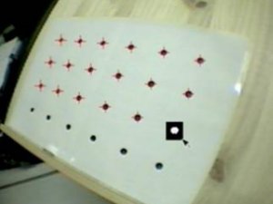
Figure 2: User marking the calibration dots.
While each dot is being found the following will appear on-screen:
-----------
Mouse Button
Left : Rubber-bounding of feature. (6 x 4)
Right : Cansel rubber-bounding & Retry grabbing.
-----------
# 1/24
# 2/24
# 3/24
# 4/24
# 5/24
# 6/24
# 7/24
# 8/24
# 9/24
# 10/24
# 11/24
# 12/24
# 13/24
# 14/24
# 15/24
# 16/24
# 17/24
# 18/24
# 19/24
# 20/24
# 21/24
# 22/24
# 23/24
# 24/24
Once all 24 dots in the image have been found click the left mouse button again. This will store the position of the dots and unfreeze the video image.
-----------
Mouse Button
Left : Save feature position.
Right : Discard & Retry grabbing.
-----------
  ### No.1 ###
  1, 1: 125.01, 102.84
  2, 1: 198.73, 96.19
  3, 1: 283.00, 94.30
  4, 1: 369.78, 99.93
  5, 1: 448.78, 110.33
  6, 1: 514.39, 123.37
  1, 2: 118.84, 173.96
  2, 2: 192.13, 171.33
  3, 2: 277.61, 171.27
  4, 2: 366.40, 175.28
  5, 2: 446.74, 181.88
  6, 2: 512.50, 189.64
  1, 3: 119.86, 246.72
  2, 3: 191.37, 248.83
  3, 3: 274.59, 251.42
  4, 3: 361.36, 253.61
  5, 3: 440.32, 255.61
  6, 3: 505.38, 257.05
  1, 4: 127.78, 313.80
  2, 4: 196.05, 319.71
  3, 4: 272.48, 327.11
  4, 4: 355.03, 325.72
  5, 4: 430.25, 324.01
  6, 4: 493.18, 320.03
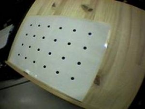
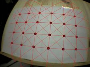
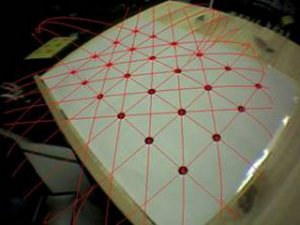
You should now take another image and repeat the process for 5-10 images from various angles and positions. The more images taken the more accurate the calibration. The figures below show typical sample images.
 |
 |
-----------
Mouse Button
Left : Grab next image.
Right : Calc parameter.
-----------
[360.0, 243.0, 174.0] 596.018289
[360.0, 243.0, 174.0] 596.018289
[360.0, 243.0, 174.0] 596.018289
[360.0, 243.0, 174.0] 596.018289
[360.0, 243.0, 174.0] 596.018289
[360.0, 243.0, 174.0] 596.018289
[360.0, 243.0, 174.0] 596.018289
[330.0, 223.0, 201.0] 590.288659
[330.0, 228.0, 201.0] 486.692482
[330.0, 233.0, 201.0] 400.390511
[325.0, 238.0, 201.0] 330.137494
[325.0, 243.0, 201.0] 276.447160
[325.0, 248.0, 201.0] 241.422442
[325.0, 253.0, 201.0] 227.895132
[325.0, 253.0, 201.0] 227.895132
[325.0, 253.0, 201.0] 227.895132
[325.0, 253.0, 201.0] 227.895132
[325.0, 253.0, 201.0] 227.895132
[325.0, 253.0, 201.0] 227.895132
[325.0, 253.0, 201.0] 227.895132
[325.0, 253.0, 201.0] 227.895132
[325.0, 253.0, 201.0] 227.895132
[325.0, 253.0, 201.0] 227.895132
[325.0, 253.0, 201.0] 227.895132
[325.0, 253.0, 201.0] 227.895132
[324.0, 253.5, 201.0] 227.334239
--------------
Center X: 324.000000
Y: 253.500000
Dist Factor: 201.000000
--------------
-----------
Mouse Button
Left : Check fittness.
Right :
1/10.
-----------
It may take a while to calculate these parameters, please be patient. The center x and y values and distortion factor are the final key values generated by the calib_dist code. These values will be different for every camera and should be written down for use in the calib_cparam program.
In order to check that these parameters are correct click the left mouse button again. This will show the first image grabbed with red lines drawn through the calibration dots. These lines should pass through the center of each of these dots (see Figure 3). Each time the left mouse is clicked the next grabbed image will be shown.
 |
 |
Running calib_cparam
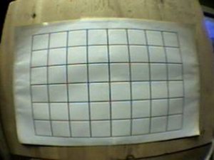
calib_cparam is used to find the camera focal length and other parameters. It uses the pattern contained in calib_cparam.pdf, a grid pattern of 7 horizontal lines and 9 vertical lines (see Figure 2). This pattern should be printed out and glued to a piece of cardboard or other rigid board.
calib_cparam is run from the console like calib_dist. Type calib_cparam at the command prompt and input the center coordinates and distortion ratio found from calib_dist:
> ./calib_cparam
Input center coordinates: X = 324
: Y = 253
Input distotion retio: F = 201
Image size (x,y) = (720,486)
1) A live video window will appear.
2) Put the calibration board in front of the camera so the board is perpendicular to the camera, all of the grid lines are visible and the grid is as large as possible (see Figure 2).
3) Click the left mouse button to grab the image. A white horizontal line will appear overlaid on the image.
4) Move the white line to overlay the top black grid line as close as possible. The line is moved up and down using the up and down arrow keys, while it is rotated clockwise and anticlockwise using the left and right arrow keys. Once the white line is aligned with the top grid line hit the enter key. This line will now turn blue and another white line will appear (see Figure 4). This process should then be repeated for all the horizontal lines.
Once the last horizontal line has been placed a vertical white line will appear and the process should be repeated for the vertical lines. The first vertical white line should be placed over the left most grid lines and the other lines placed from left to right (see Figure 5).
The ordering of lines is very important. They should be placed from top to bottom and then from left to right until all 16 lines have been drawn on the screen.
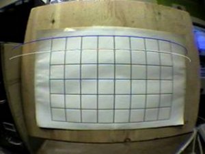 Figure 4: Horizontal Line Placement |
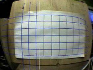 Figure 5: Vertical Line Placement |
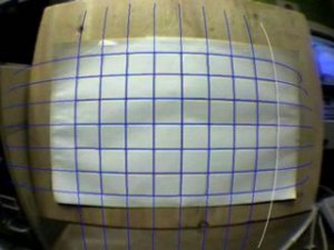
Figure 6: Final Line Placement
6) Repeat the process five times, moving the calibration pattern a total of 500mm away from the camera. After the fifth calibration step the program will automatically calculate the camera parameters. You will be prompted for a file name to store these parameters in:
point_num = 315
--------------------------------------
SIZE = 720, 486
Distotion factor = 324.000000 253.000000 201.000000
372.97979 -24.50134 248.86941 0.00000
0.00000 327.03507 122.42421 0.00000
0.00000 0.00000 1.00000 0.00000
--------------------------------------
Input filename: wideAngleKeyence.dat
Once the values are stored in a camera data file hit the right mouse button to quit.
By changing the name of this camera data file to camera_para.dat and placing it in the bin/Data directory it can be used immediately in the ARToolKit sample programs. Calibrating your camera should give improved tracking results.
The distance between the grid lines in the calib_cparam.pdf pattern is exactly 40mm, while the pattern has to be moved back 100mm for each measurement and the measurements have to be repeated five times. These values are all fixed in the source code calib_cparam_sub.c in the util/calib_cparam directory.
If you want to change the distance between grid lines the following source code should be modified:
inter_coord[k][j][i+7][0] = 40.0*i;
inter_coord[k][j][i+7][1] = 40.0*j;
inter_coord[k][j][i+7][2] = 100.0*k;
where 40.0 is the current distance, and the 100.0 is the distance the pattern should be moved back from the camera each time. The number of measurements that need to be taken can be modified by changing the variable:
*loop_num = 5;
> calib_cparam2
Input the length between each markers: 40

-----------
Mouse Button
Left : Grab image.
Right : Quit.
-----------
After that repeat the same instruction of calib_dist program.